
Phensa Engineering logo
Marine Technical Drafting banner

Marine Technical Drafting

Drafting Capabilities

The Drawings That Build a Vessel

Every vessel is defined by a set of controlling drawings — from the geometry of the hull to the routing of exhaust gas. These are the marine drafting deliverables our team produces, each prepared to classification society and IMO standards.

  1. General Arrangement Plan — marine drafting sample
    01

    General Arrangement Plan

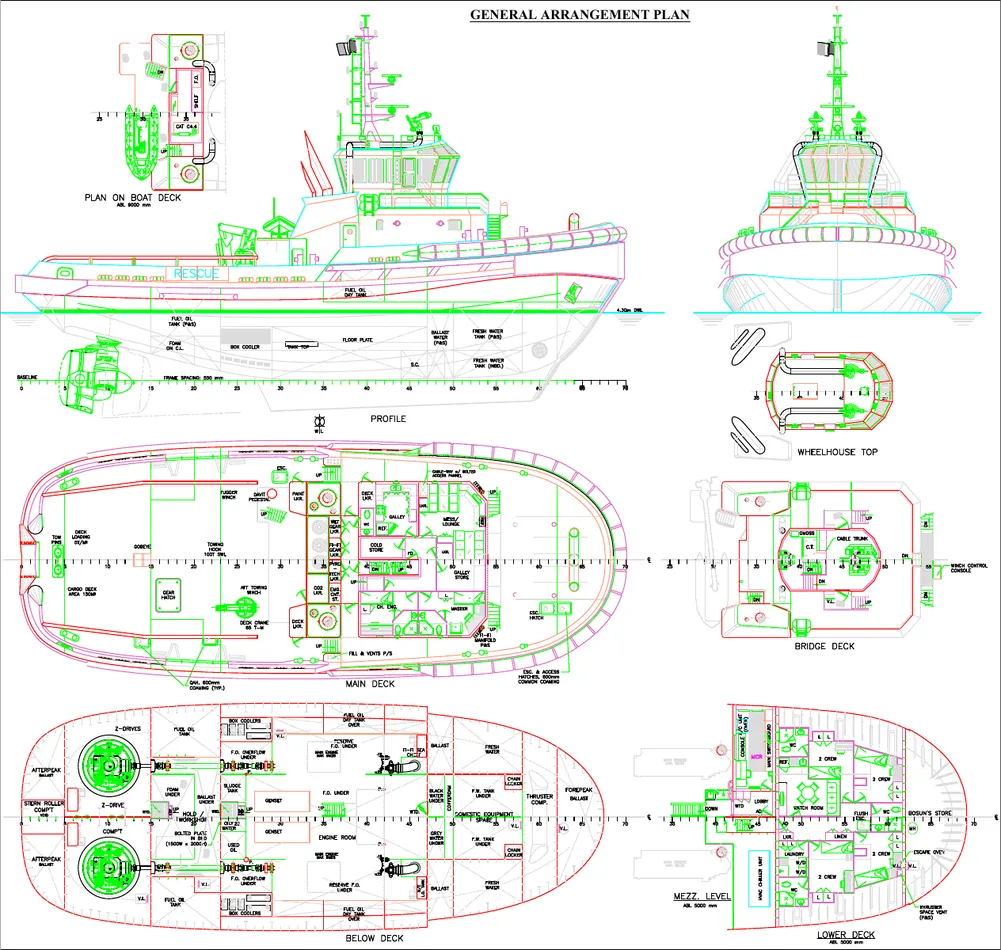
    The General Arrangement (GA) of a ship is the backbone of marine design and operations — it defines how every space, system, and function is organized, ensuring safety, efficiency, and compliance throughout the vessel’s lifecycle. Without a GA plan, shipbuilding and operation would lack coordination and regulatory approval.

    General Arrangement (GA) drawings provide the overall spatial layout of the ship, including profile, deck plans, and sections. They show the placement of cargo holds, machinery spaces, crew accommodations, tanks, and passageways, and serve as the master reference document for designers, builders, owners, and regulators.
  2. Lines Plan — marine drafting sample
    02

    Lines Plan

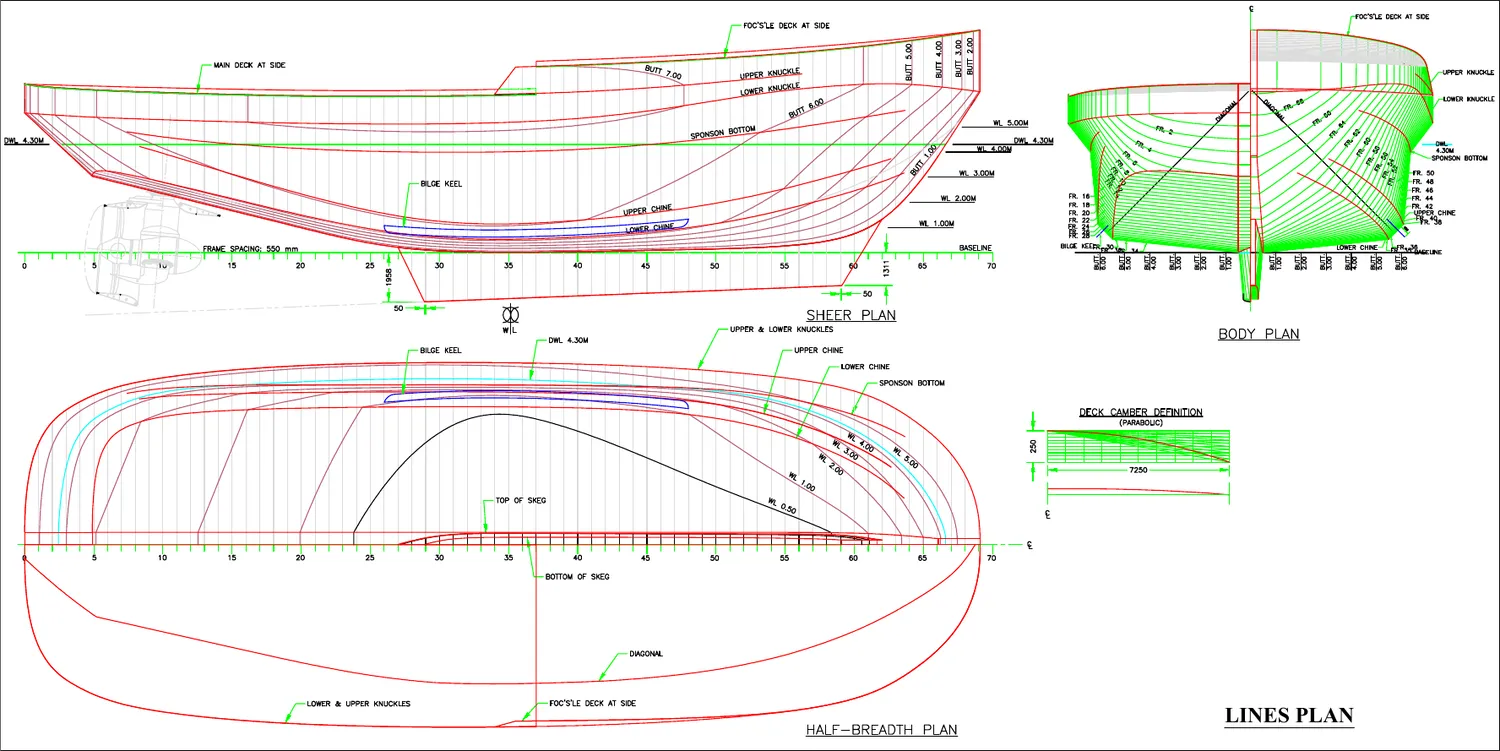
    In the marine industry, a ship’s lines plan is the foundation of hull design and construction, serving as the geometric blueprint that defines the vessel’s shape, stability, resistance, and structural layout. Without it, accurate calculations of displacement, buoyancy, and strength would be impossible.

    A lines plan is a fundamental naval architectural drawing consisting of three orthogonal projections—Body Plan (transverse sections showing hull shape from bow to stern), Sheer Plan (side profile showing keel, deck, and sheer line), and Half-Breadth Plan (top view showing waterlines at various drafts). It serves as the basis for hydrostatics & stability calculations (displacement, buoyancy, coefficients, GZ curves), influences resistance & powering (fuel economy and propulsion efficiency), provides structural reference for steel cutting and lofting, ensures compliance through classification & regulation approvals, and illustrates design evolution from fine bow to fuller midship to tapered stern—balancing strength, speed, and cargo capacity.

  3. Profile, Deck and Bottom Plan — marine drafting sample
    03

    Profile, Deck and Bottom Plan

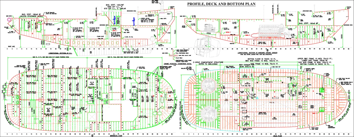
    In ship design, the Profile, Deck, and Bottom Plans are fundamental drawings that define the vessel’s geometry, strength, and functionality. Together, they provide a complete picture of the ship’s layout, structural integrity, and operational arrangement.

    The Profile Plan provides a longitudinal vertical view of the vessel, displaying its overall length, depth, sheer line, deck levels, bulkheads, superstructures, and openings, and is essential for classification society approval and defining structural continuity. The Deck Plan offers a horizontal view of each deck, showing compartment arrangements, access routes, safety equipment, and escape provisions, serving as a vital tool for operational planning and compliance with SOLAS safety regulations. The Bottom Plan details the ship’s bottom plating and framing, including double bottom tanks, stiffeners, girders, and floors, ensuring hull strength, ballast arrangements, and damage stability. Together, these plans align with the Lines Plan to maintain hull geometry consistency, undergo review by classification societies such as ABS, DNV, and IRS, and integrate into the General Arrangement and Structural Plans required for shipbuilding approval.

  4. Deckhouse Structure — marine drafting sample
    04

    Deckhouse Structure

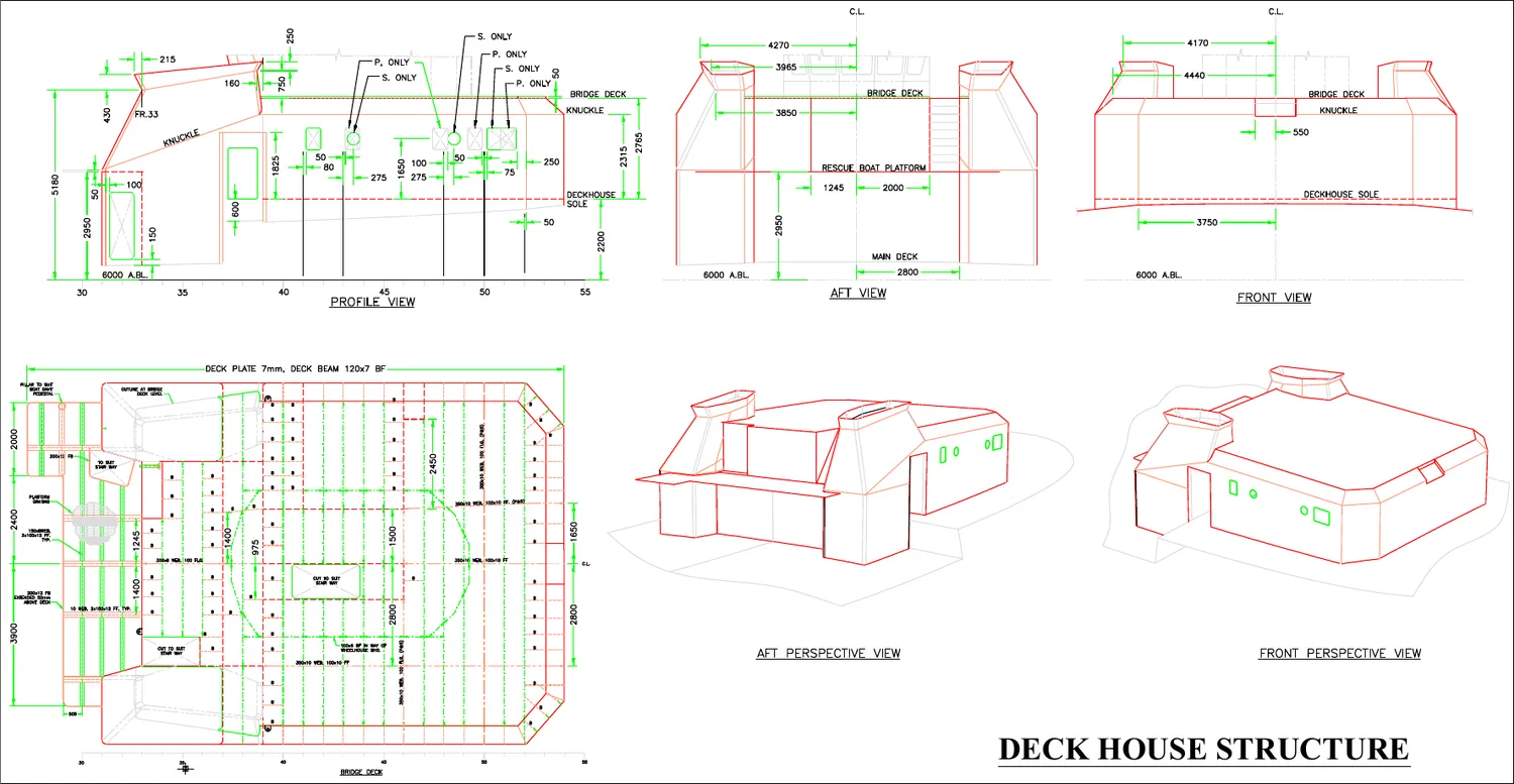
    In the marine industry, the deckhouse structure of a ship refers to the enclosed superstructure built above the main deck, housing essential spaces like navigation bridge, crew accommodation, control rooms, and service areas. It is designed for strength, safety, and functionality while minimizing weight and wind resistance.

    The deckhouse serves as a multifunctional structure on ships, with the navigation bridge located at its top to provide visibility and operational control. It houses crew accommodation including living quarters, mess rooms, and recreational spaces, alongside control and service rooms such as the engine control room, communication centers, and safety stations. Designed to offer protection against harsh marine environments, the deckhouse is typically fabricated from steel or aluminum with welded construction for strength and watertight integrity. Its structural features include lightweight yet rigid design, streamlined form to reduce wind resistance, and integration with the main deck and hull girder to enhance overall ship strength. Safety measures such as fire-resistant bulkheads, watertight doors, and escape routes are standard.

  5. Wheel House — marine drafting sample
    05

    Wheel House

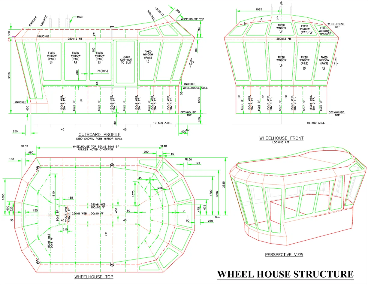
    In the marine industry, the Wheel House (or Bridge) is the ship’s command center — a structural space located high on the superstructure, designed to provide maximum visibility and house all navigation, communication, and control systems essential for safe vessel operation.

    The wheelhouse integrates navigation systems (radar, GPS, ECDIS, autopilot), steering and control (helm, propulsion, thrusters), communication equipment (VHF, satellite, intercoms), safety monitoring (alarms, watertight/fire doors, lighting), and documentation storage (papers, permits, emergency cash). Structural standards are governed by the IMO and classification societies, specifying visibility, escape, and accommodation rules. Modern wheelhouse design emphasizes ergonomic layouts to reduce crew fatigue and enhance operational efficiency.

  6. Engine Room or Machinery Room Arrangement — marine drafting sample
    06

    Engine Room or Machinery Room Arrangement

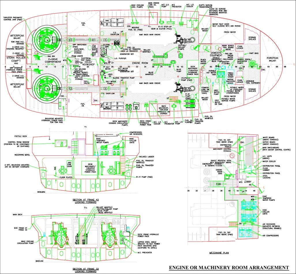
    In the marine industry, the engine room layout is the heart of a ship’s operations — a compact but highly complex space housing propulsion machinery, power generation systems, fuel handling, cooling, and safety equipment. Its design balances efficiency, accessibility, and safety while maximizing cargo or passenger space.

    The engine room layout integrates key components including the centrally positioned main engine, propulsion systems, auxiliary machinery, fuel handling units, cooling and lubrication circuits, and safety/fire systems, all arranged according to vessel type—aft positioning for cargo ships, distributed layouts for passenger vessels, compact designs for container ships—with principles of accessibility and redundancy ensuring safe, efficient, and reliable operation.

  7. Towing Arrangement — marine drafting sample
    07

    Towing Arrangement

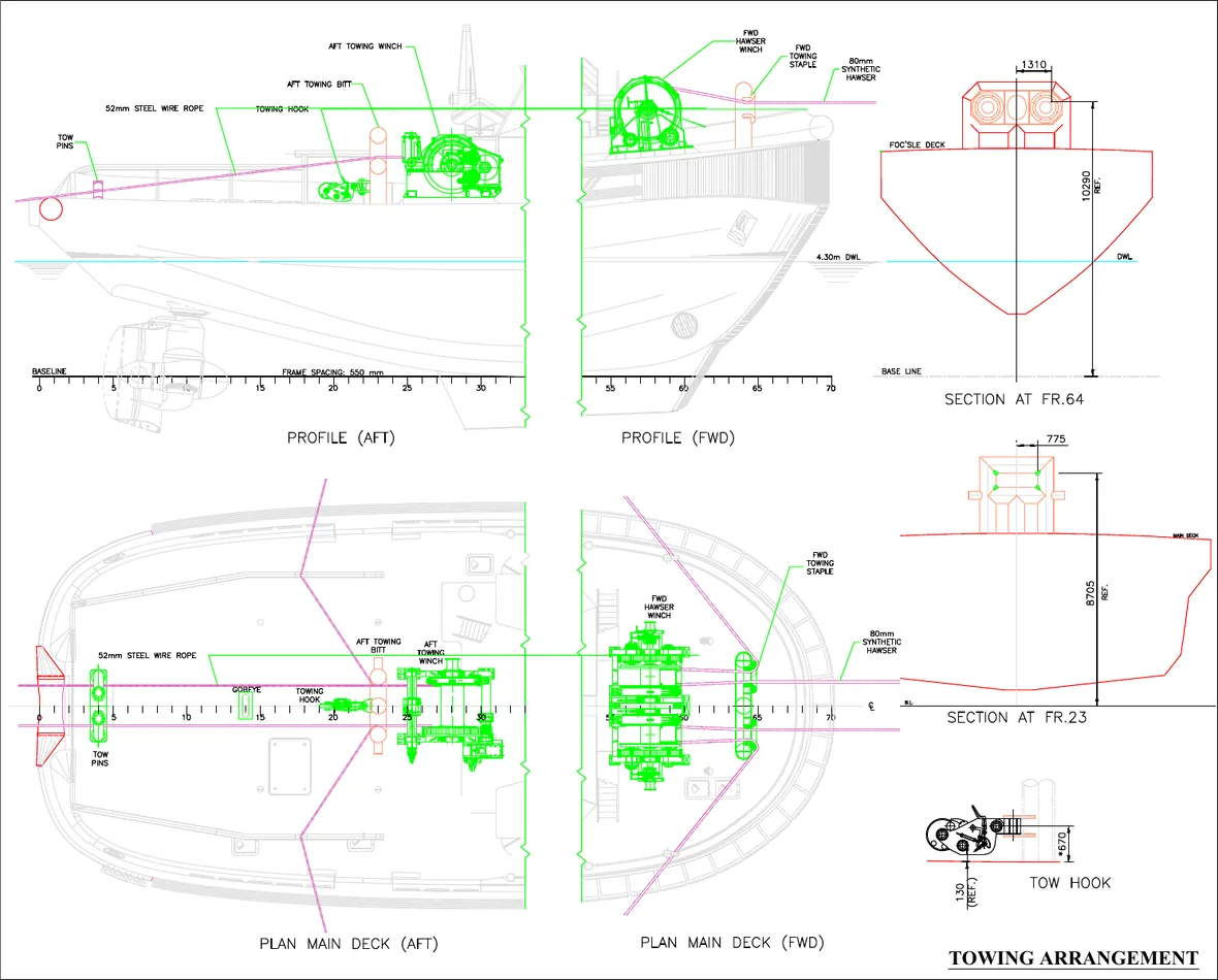
    In the marine industry, a ship’s towing arrangement is a critical safety system designed to enable controlled towing during emergencies such as engine failure, grounding, or salvage operations. It consists of strong points, fairleads, towing winches, and emergency towing gear located at both the bow and stern, ensuring redundancy and compliance with IMO and ISO standards.

    Emergency towing arrangements consist of reinforced strong points (bollards, bitts, pad eyes), heavy-duty fairleads, mechanized towing winches, and complete emergency gear (ropes, shackles, stoppers, chains), with bow and stern flexibility; all designed and documented per IMO, ISO, and SOLAS, supported by an Emergency Towing Booklet detailing ship particulars, rigging diagrams, certified capacities, and operational readiness requirements.

  8. Engine Room Ventilation — marine drafting sample
    08

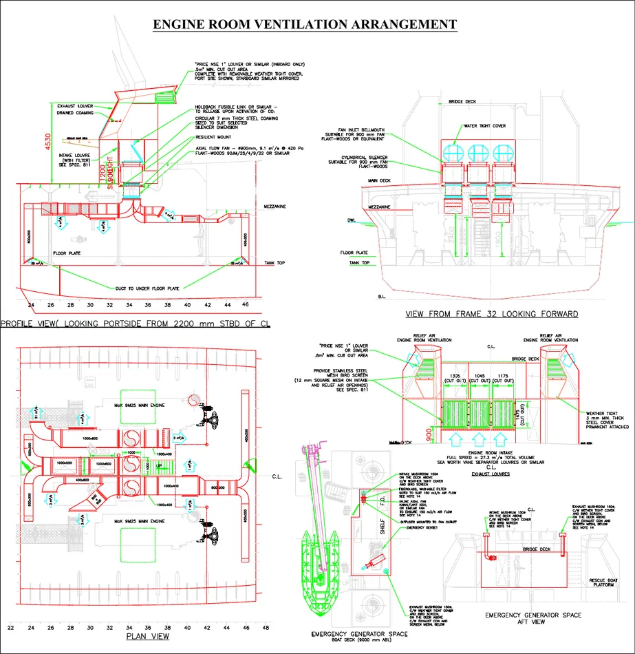
    Engine Room Ventilation

    Engine room ventilation in ships ensures safe operation by supplying combustion air to engines and removing heat, fumes, and contaminants. Mechanical ventilation systems use fans and ducting to maintain air changes per hour (ACH) as per SOLAS regulations, keeping temperatures below 45–50°C and preventing hazardous atmospheres.

    Mechanical ventilation systems in engine and other machinery rooms provide combustion air, ensure heat removal, and maintain air changes as per SOLAS and class society rules. Heat removal limits ambient temperature rise to 10–15°C, with a maximum of 45–50°C. Air change requirements are 30 ACH for main engine rooms and emergency generators, and 20 ACH for auxiliary machinery and boiler rooms. System components include supply fans, exhaust fans, louvers and filters, ductwork, dampers and silencers, and emergency shut-offs. Key design considerations include combustion air margins (+15–20% for peak loads), maintaining ambient <50°C, pressure drops of 250–600 Pa, and safety compliance with external emergency shut-off operation.

  9. Shafting, Propulsion and Steering Arrangement — marine drafting sample
    09

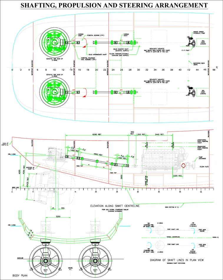
    Shafting, Propulsion and Steering Arrangement

    In the marine industry, shafting, steering, and propulsion form the backbone of how a ship moves and maneuvers. Shafting transmits engine power to the propeller, propulsion converts that power into thrust, and steering systems (rudder and controls) direct the vessel’s course. Together, they ensure safe, efficient, and reliable navigation.

    The ship’s shafting system transmits engine torque and axial thrust to the propeller via thrust, intermediate, and tail shafts supported by bearings and sealed at the stern tube, with couplings ensuring smooth power transfer to fixed- or controllable-pitch propellers, while steering is achieved through a hydraulically or electro-hydraulically actuated rudder integrated with bridge-controlled autopilot and monitoring systems for safe navigation.

  10. Main Engine Exhaust Piping — marine drafting sample
    10

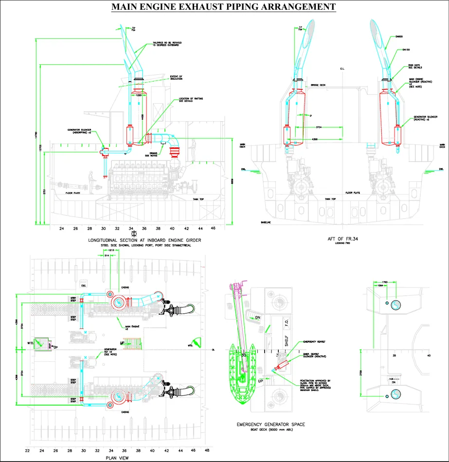
    Main Engine Exhaust Piping

    In ships, the main engine exhaust piping arrangement is designed to safely discharge combustion gases while minimizing backpressure on the turbocharger, recovering waste heat, and ensuring compliance with noise and safety standards. The system typically routes exhaust gases from the engine cylinders through turbochargers, exhaust gas boilers, silencers, and expansion joints before venting to the atmosphere.

    Main engine exhaust piping comprises an exhaust gas receiver, turbocharger, exhaust gas boiler, silencer, spark arrester, and expansion joints, designed to maintain gas velocity (35–50 m/s at MCR), limit backpressure (<350 mm WC), manage outlet temperatures (400–650 °C, reduced to 50–70 °C in wet systems), control noise per IMO standards, and resist corrosion using marine-grade alloys.

  11. Mast Arrangement — marine drafting sample
    11

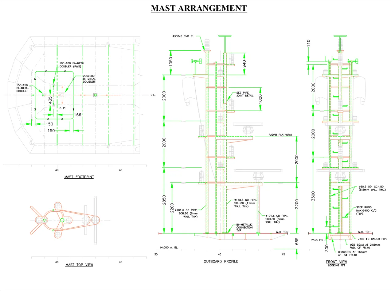
    Mast Arrangement

    In the marine industry, a ship’s mast arrangement refers to the structural and functional layout of masts that support navigation, communication, and operational equipment. Modern ships use steel truss masts to carry radar, antennas, lights, and signal systems, while traditional sailing ships used wooden masts to support sails.

    Traditional sailing ships featured Foremast near the bow with bowsprit, Mainmast tallest and central carrying the largest sails, and Mizzenmast aft aiding balance. Masts were divided into lower, top, topgallant, and royal sections, serving propulsion, lookout, and signalling functions.

    Modern vessels employ steel truss structures above the bridge deck or superstructure, supporting antennas, radar, navigation lights, and signals. These provide communication, navigation, and safety, while naval ships integrate advanced defence and surveillance systems. Arrangements typically include one or two masts, with larger warships adopting complex multi-level designs.

Need a Drawing Package?

Tell us the vessel type and the deliverables you need, and we will scope the drafting package.

Naval Architecture